Super User
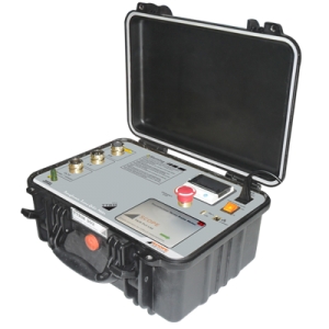
SCOPE introduces 25 A state of the art precision winding resistance meter, specially designed for field testing as well as factory testing of large transformers up to 500 MVA. Winding resistance value of transformer and rotating machine are directly displayed on 5.7” TFT display. TRM 25 is designed to work in live EHV switchyard conditions, ensuring operator’s safety and repeatability of results. Maintenance time saving is ensured by one time connection to transformer with simultaneous resistance measurement of three / six windings, measurement of resistances of all taps with automated tap change and demagnetization facility. The meter is protected against the back-EMF offered by large inductive windings.
Features
- Can measure DC winding resistance of large rotating machines, highly inductive test objects like Transformer, Generators and Motors etc.
- 25A DC current makes it possible to measure low resistances with high accuracy.
- One time connection to either all windings of primary and / or secondary. Simultaneous measurement reduces connection and measurement time.
- Change in winding resistance, short or open windings can be detected from measured values.
- Automatic temperature measurement and temperature corrected value calculation.
- Measurements of winding resistance of all taps of phases in one go. Recoding, printing and storage of results.
- OLTC contact opening and compete OLTC performance test facility. Testing of either single or three phases in one test. Single report generation.
- To know condition of OLTC contacts, OLTC mechanism, transition resistor.
- Discharges and demagnetizes the object after test.
Specifications
| Parameter | TRM 25/ TRM 25+ |
| No of Channels | 3/6 Current Channels, 3/6 Volatge Channels , 1 temperature Channel |
| Connections | One time connection to primary or secondary winding of transformer |
| Current Ranges | 25A, 10A, 5A, 1A, 100mA, 10mA |
| Resistance Ranges | Up to 2000 Ω (Auto ranging) |
| Resolution | 4 ½ digit |
| Accuracy | Value ± 0.5% ± 5 counts |
| Open Circuit Voltage | 50 V |
| Demagnetization Facility | Yes |
| Display | 5.7” TFT display with touch screen |
| Printer | 58 mm, Inbuilt thermal printer |
| Communication Port | Ethernet for PC communication |
| Data Port | USB for extrernal memory stick connection |
| External Control | Possible via Notebook PC through Ethernet port and software |
| Temperature measurement | Range 0 to 100 deg, Accuracy ± 1 deg, Resolution 0.1deg |
| Temperature correction | For Aluminium & Copper |
| Temperature Input Channel | Compatible to accept RTD input |
| User Interface | Resistive touch screen |
| Back EMF Protection | Yes. Automatic protection after measurement and during accidental disconnection of current path. Protection operates even if Mains supply fails. |
| Discharge Facility & Indication | Automatic Discharge of DUT & messages on screen |
| Tap Changer Test | Detects discontinuity during tap changer test |
| OLTC Test Facility(Optional) | OLTC test facility with current v/s time graph, Single or Three Phases simultaneously. Available in control through PC option only. |
| OLTC current Ranges | 25A, 10A, 5A |
| Protection | Shut down of power source on Over voltage, Over current,Over temperature |
| Indications | Polarity reversal, Test connection continuity and discharge |
| Diagnostics Check | At power On instrument does self-check of channels and shows the message |
| Test Leads | Measuring leads, AC supply, earth leads and temperature sensor lead |
| Operating Environment | -10°C to 50°C, 95% RH (non condensing) |
| Storage Temperature | -20°C to 60 °C |
| Heat Run test | Yes |
| Delta connection Measurement | values of each arm of delta winding is calculated and displayed |
| One side earthing | Instrument is able to do the measurement with one side earthing (with Neutral earthing) |
| Input Supply | 110V AC ±15% 50/60 Hz ±10% Or 220V AC ±15% 50/60 Hz ±10%. |
| Dimensions | 630 x 500 x 302mm |
| Weight | 22 Kg. Approx |
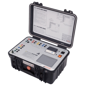
HISAC Swift - Circuit Breaker Operational Analyser is meant for checking the performance of the MV Circuit Breakers. The Analyser contains various intelligent measuring modules designed for measuring parameters such as contact timings of Main/PIR & Auxiliary contacts, Close/Trip Coil Current characteristics and Static Contact Resistance of R, Y & B poles simultaneously. The results can be directly viewed on the TFT touch screen display in graphical as well as numerical form. It is possible to print the graph on a built-in thermal printer or download record to PC for further analysis on CPLOT software. This all in one instrument is best suited for gang operated CBs.
Features
- Type Tested as per IEC 60068, IEC 61326 & IEC 61010-1. CE marked
- Breaker information data entry and system settings entered into the kit through the touch screen keyboard
- Operations: C, O, C-O, O-C, O-C-O with configurable delays
- Contact timing of 3 Main and 3 PIR Contacts with 0.05mS resolution
- One internal channel to measure close and Trip coil current
- 3 multiplexed channels to measure Static Contact resistance with 0.1μΩ resolution and range up to 2Ω
- CPLOT software provided with instrument for further analysis on PC
- TFT Color LCD screen with touch, In-built printer, In-built memory for internal data storage
- Instrument housed in IP67 molded case
Specification
| Parameter | HISAC Swift |
| Contact Channels | 6:1 Main + 1 PIR pole, 3 poles simultaneously |
| Sampling Speed | 20kC, 10kC, 5kC, 2kC & 1kC selectable |
| Trigger Options | Open, Close, C-O, O-C, O-C-O, delay between operations selectable |
| Auxillary Contacts | 2: Dry/Wet selectable, 15V to 300V DC (for Wet Channels) |
| Coil Current | 1: Trip /Close Coil Current, 1,2,5,10,25 & 50A DC |
| Contact Resistance | 3: Multiplexed channels, 10A Max |
| Breaker Control | Two solid state contacts rated at 50A, 300V AC/DC for breaker operation |
| Display | 320 x 240 Pixel, 5.7" Color TFT LCD with LED back-lit, Touchscreen |
| Power |
90-260V AC, 47-63Hz, 25 VA (approx) |
| Communication Port | USB port, for data download |
| Environment | 0 to 50°C, Upto 95% RH (Non condensing) |
| Dimensions | 415 x 230 x 200 mm |
| Instrument Weight | 10 Kg |
SCOPE’s iconic SCOT series Circuit breaker time interval meter is in all new super light avatars, based on cutting edge micro-controller & embedded technology. SCOT M3K+ incorporates some state of the art hardware & smart software features making it a must have tool for testing & maintenance engineers.It is compact, lightweight and reliable instrument used for measurement of operating time of all types of HV and EHV circuit breakers under live switchyard conditions.
SCOT M3K+ measures and displays CLOSE, OPEN and CLOSE-OPEN times of Main contacts of 3 poles connected end to end, simultaneously. Ideally suitable for CBs with single break per pole.
Features
- A radically new design makes SCOT the lightest available CB Time Interval Meter
- High sampling frequency of up-to 10 KHz offers high timing resolution of 0.1ms
- Mains as well as rechargeable Li-ion battery operated. In built battery monitor and cut off circuit for protection
- Real Time Clock, Memory and Printer, Automatic Test time stamping
- PC Downloading & Analysis including ‘Trend Analysis’ possible with “CData SCOT+” Software supplied with kit
- Create CB Identification data (CB Library) on PC and upload to instrument - Save the test results in respective CB folder in kit - Download the same to PC in similar folder structure
- Instrument debug options like Contact Status Check, Command Check, Memory Check, PC Communication Check is provided
- Simple operation - Tests can be conducted even by technicians
- Supplied with rugged test lead set, suitable for testing EHV CBs
- Enclosed in ultra-rugged IP67 class hard molded case
Specifications
| Parameter | SCOT M3k+ |
| Contact Timing Channels | 3 (Main contacts of 3 poles connected end to end, simultaneously) |
| Sampling Speed | 10kHz, 5kHz, 2kHz, 1kHz & 100Hz - Selectable |
| Timing Range | 1s, 2s, 5s, 10s & 100s respectively for above Sampling Speeds |
| Resolution | 0.1ms, 0.2ms, 0.5ms, 1ms & 10ms respectively for above Sampling Speeds |
| Accuracy | Value ± 0.05% ± 1 Digit |
| Breaker Control | Two solid state contacts rated at 300V, 35A AC/DC for breaker operation |
| Trigger Options | Close, Open, Close-Open |
| Display | 4 Line X 20 character backlit LCD |
| Memory | 100 records, Internal |
| In-built Battery | Li-Ion, 11.1 V, 4 Ah |
| Power |
Input to Battery Charger - 90 to 275V AC, 50/60Hz ± 10% ;100 to 300V DC Charger output - 13.5V DC, 1000mA Max.; Instrument consumption - 15VA |
| Communication Port | USB |
| Software | CData SCOT+ : For PC Downloading & Analysis, Windows TM based |
| Environment | 0 to 50°C, Upto 95% RH (Non condensing) |
| Dimensions | 300 x 250 x 200 mm |
| Instrument Weight | 5 Kg |
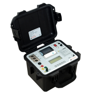
SCOPE’s iconic SCOT series Circuit breaker time interval meter is in all new super light avatars, based on cutting edge micro-controller & embedded technology. SCOT MXP+ incorporates some state of the art hardware & smart software features making it a must have tool for testing & maintenance engineers. It is compact, lightweight and reliable instrument used for measurement of operation times of all types of HV and EHV circuit breakers under live switchyard conditions.
SCOT MXP+ measures, displays and prints CLOSE, OPEN and CLOSE-OPEN time of 2 Main + 2 PIR contacts per pole, 3 poles simultaneously, ensuring measurement of 6 Main + 6 PIR contacts simultaneously. Ideally suitable for CBs having PIR contacts & multiple breaks per pole.
Features
- A radically new design makes SCOT the lightest available CB Time Interval Meter
- High sampling frequency of up-to 10 KHz off ers high timing resolution of 0.1ms
- Mains as well as rechargeable Li-ion battery operated
- Real Time Clock, Memory and Printer, Automatic Test time stamping
- PC Downloading & Analysis including ‘Trend Analysis’ possible with “CData SCOT+” Software supplied with kit
- Create CB Identifi cation data (CB Library) on PC and upload to instrument - Save the test results in respective CB folder in kit - Download the same to PC in similar folder structure
- Instrument debug options like Contact Status Check, Command Check, Memory Check, PC Communication Check is provided
- Simple operation - Tests can be conducted even by technicians
- Supplied with rugged test lead set, suitable for testing EHV CBs
- Enclosed in ultra-rugged IP67 class hard molded case
Specifications
| Parameter | SCOT MXP+ |
| Contact Timing Channels | 12 (Up-to 2 Main + 2 PIR contacts per pole, 3 poles simultaneously, i.e. 6 Main + 6 PIR contacts simultaneously) |
| Sampling Speed | 10kHz, 5kHz, 2kHz, 1kHz & 100Hz - Selectable |
| Timing Range | 1s, 2s, 5s, 10s & 100s respectively for above Sampling Speeds |
| Resolution | 0.1ms, 0.2ms, 0.5ms, 1ms & 10ms respectively for above Sampling Speeds |
| Accuracy | Value ± 0.05% ± 1 Digit |
| Breaker Control | Two solid state contacts rated at 300V, 35A AC/DC for breaker operation |
| Trigger Options |
Close (C), Open (O), Close -Open (CO) O - 0.3s - CO - 3min - CO (Available only on request) |
| Display | 4 Line X 20 character backlit LCD |
| Printer | In-built, 58 mm thermal printer |
| Keypad | 5 keys |
| Memory | 100 records, Internal |
| In-built Battery | Li-Ion, 11.1V, 4Ah |
| Power |
Input to Battery Charger - 90 to 275V AC, 50/60Hz ± 10% ;100 to 300V DC Charger output - 13.5V DC, 1000mA Max.; Instrument consumption - 15VA |
| Communication Port | USB |
| Software | CData SCOT+ : For PC Downloading & Analysis, WindowsTM based |
| Environment | 0 to 50°C, Upto 95% RH (Non condensing) |
| Dimensions | 300 x 250 x 200 mm |
| Instrument Weight | 5 Kg |
SCOPE introduces state of the art precision single phase Transformer Turns Ratio Meter (TTRM ) designed for field testing as well as factory testing of power transformers, instrument transformers and distribution transformers of all types. TTRM 102 along with turns ratio, measures ratio deviation, phase angle deviation, magnetizing current and detects tap-position of single phase transformer in charged switchyard condition. The range of AC voltage selection offers high accuracy in measurement.Both the instrument have in-built TFT display with touch screen and thermal printer. The user friendly, simple instrument makes the testing more easy. With the touch keypad it is possible to enter required DUT information.The ratio results are displayed with % error. Internal non-volatile memory gives the provision of storing test results.Further data can be downloaded to PC or copied to memory stick through USB port provided.
The C-Trans-software, gives the flexibility to download the stored results to PC and do the further analysis and report generation.
Features
- Different voltage ranges provided for more accurate results
- 5.7” TFT display with touch screen and simple menus to operate TTRM
- Facility to configure transformer ID and details
- Automatic OLTC operation for tap change
- Date and time stamping to results
- In-build memory to store the test results
- Thermal printer to take quick print out for record
- Ethernet port for PC interface to transfer records to PC Software
- Mass storage device (USB 2.0) interface for copying records in pen drive
- Lightweight, portable instrument household in rugged moulded case
Specifications
| Parameter | Test Voltage | Range | Resolution | Accuracy | |
| 1 |
Ratio | 10 V | 0.8000 – 9.9999 | 0.0001 |
0.05 % |
| 10.000 – 99.999 | 0.001 |
0.05 % |
|||
| 100.00 – 999.99 | 0.01 | 0.05 % | |||
| 1000.0 – 1500.0 | 0.1 | 0.05 % | |||
| 1500.1 – 2000.0 | 0.1 | 0.1 % | |||
| 2000.1 – 4000.0 | 0.1 | 0.2 % | |||
| 40 V | 0.8000 – 9.9999 | 0.0001 | 0.05 % | ||
| 10.000 – 99.999 | 0.001 | 0.05 % | |||
| 100.00 – 999.99 | 0.01 | 0.05 % | |||
| 1000.0 – 4000.0 | 0.1 | 0.05 % | |||
| 4000.1 – 9999.9 | 0.1 | 0.25 % | |||
| 10000 - 13000 | 1 | 0.25 % | |||
| 100 V | 0.8000 – 9.9999 | 0.0001 | 0.03 % | ||
| 10.000 – 99.999 | 0.001 | 0.03 % | |||
| 100.00 – 999.99 | 0.01 | 0.05 % | |||
| 1000.0 – 4000.0 | 0.1 | 0.05 % | |||
| 4000.1 – 9999.9 | 0.1 | 0.15 % | |||
| 10000 – 13000 | 1 | 0.15 % | |||
| 13001 - 20000 | 1 | 0.20 % | |||
| 2 |
Excitation Current |
10 V | 2000 mA | 0.1 mA | ± 1 mA |
| 40 V | 500 mA | 0.1 mA | ± 1 mA | ||
| 100 V | 200 mA | 0.1 mA | ± 1 mA | ||
| 3 | Phase Deviation |
10V / 40V / 100 V |
± 180 Degree | 0.01 Degree | ± 0.05 Degree |
| Parameters | TTRM 102 |
| No of channels | single HV channel and single LV channel |
| Test Voltages | 10V, 40V and 100V AC selectable voltages |
| Measurements | Ratio, Ratio error, Phase Angle Deviation, Excitation Current |
| OLTC Control | Raise and Lower control to operate OLTC |
| Test Results Display | (TFT) display, Thermal Printer. |
| Test Leads | Suitable to test EHV Transformers |
| Printer | Inbuilt Thermal Printer |
| Paper | Thermal, 58 mm wide roll form |
| Memory | Inbuilt memory, can store 50000 records, with date and time stamping. USB port to copy record in pen drive |
| Power | (110V ± 15%) / (60Hz ± 10%) OR (230V ± 15%) / (50Hz ± 10%), 75VA.. |
| Communication Port | Ethernet port. |
| Housing | Fitted in moulded case |
| Environment | 0: -20°C to 55°C 95%RH (non-condensing) Electrical noise normally found in charged EHV switchyards |
| Dimensions | 435 X 315X 175 mm. (Max.) |
| Weight | 10 Kg Approx |
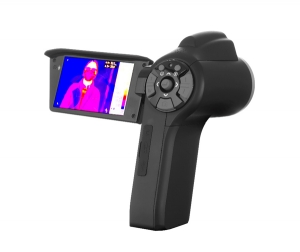
TI 160-P5 is a special thermal imaging camera for human body temperature measurement only. Its has Accurate temperature measurement, real-time imaging, ability to quickly lock the hot-spot. It is been widely used in airports, docks,railway stations, schools, shopping malls and other public places to check human body temperature abnormalities. Palmetto design, compact and lightweight, integrated visible light function. Reliable performance and accurate temperature measurement can effectively improve the efficiency of detection.
Features
- 160 x 120 un-cooled detector
- Measuring accuracy 0.5°C
- Fusion and overlay of the thermal image & visible image
- 40s voice record & alarm
- Multi-mode for temp. measurement, max./min./avg temp, auto tracking,isotherms analysis
- 3.2" ,270° rotatable and foldable LCD
- Motorized lens, auto focus
- Tiny size, light weight 400 gms
- Free professional analysis software
Specifications
| Parameters | TI160-P5 |
| Field of View | 24 x 18° |
| Minimum Imaging Distance | 15 cm |
| Resolution | 160 x 120 pixels |
| Spectral range | 7.5 - 14 µm |
| NETD |
50mk |
| IFOV | 2.3mrad |
| Focus | Auto/motor |
| lens (optional) | 45°×34°/15cm, 12°×9°/1m |
| Display | 3.2", 270° tiltable, resolution 800 x 480 pixels |
| In built Visual Camera | 3.0 MP, CMOS, Auto Focus, 1 LED Supplementary light |
| Zoom | 1x - 4x continuous |
| Contrast / brightness | Auto/Manual |
| Color Palettes | 12 palettes(including iron, rainbow, white hot and black hot etc.) |
| Temperature range | +30°C to 45°C |
| Measurement accuracy | ±0.5°C |
| Measurement model | 4 adjustable boxes with max./min./avg temperature value |
| Measurement correction | Auto/Manual |
| Emissivity correction | Adjustable from 0.01 to 1.0 or selected from list of materials |
| Setting | Date/time, temperature unit °C/°K /K |
| Internal memory | Built-in flash card, up to >700 images |
| SD Card | 8G SD card, up to >11200 images |
| Storage mode | Auto/Manual store image in frame |
| Operation | with single phase 230 V ±10% or battery |
| Battery life | 3 hrs continuous |
| Operating temperature | -20°C to +50°C |
| Storage temperature | -40°C to +70°C |
| Humidity | 95% non-condensing |
| Size | 158mm×62mm×54mm |
| Weight | ≤0.4kg (with battery and standard lens) |
Prima Series is designed for Primary Current Injection Testing of Current Transformers, Protection Relays & Circuit Breakers during their Factory Test, Commissioning and Routine Testing.
It is also tests the secondary current of Current Transformers and for other applications that require variable high currents.
The Kit is designed for most optimal use of man and machine and is suitable to work in live switch yard conditions. Kit to be used for the injection of high current to the Primary side of the CT as per the guidelines of IEC 60044 / IEC 61869 and is suitable to work in live switch yard conditions up to 765kV.Prima consists of a separate Control Unit and Loading Transformer, it enables user to take the Loading Transformer nearest to the DUT’s terminal.
The weight of both the Output lead and overall kit reduces considerably. The kit has trolley / wheel mounted arrangement for easy transportation. The innovative design of Prima gives the ultimate flexibility to the user to use the full capacity of the Loading Transformer by adjusting the output voltage and current as per requirement.
Features
- A radically new design makes Prima the lightest available kit in its category
- Modular & Rugged design for easy transportation
- Suits equally to Utilities, OEMs, Test Labs as well as Testing & Commissioning Companies
- User friendly and simple standalone operation with Timer Function
- Continuous Current output up to 1000A / 2000A / 3000A AC
- Configurable current output of ‘Rated’, ‘Rated/2’ & ‘Rated/4’
- Auto cut-off if the output current exceeds 110% of the selected range
- Course Control through ‘Raise’ & ‘Lower’ Switch and Fine Control through rotary knob
- Secondary Current measurement function through Clamp-on CT – first of its kind in its category
- Selectable Secondary Current Ranges of 1A, 5A & 10A
- Safety features like input supply fuses, MCBs, Power ON indications
- Automatic Variac Zero operation at power on
- Slow-blow fuse at mains input and MCB for overload protection
- Output On-Off function in Control Unit
- Trolley with collapsible handle for easy transportation
- Additional lifting handles provided for easy lifting of the kit
- Specially designed highly flexible flameproof output cable with higher current rating
Specifications
| Parameters | Prima 1 | Prima 2 | Prima 3 |
| Max Current | 1000A AC | 2000A AC | 3000A AC |
| Max Capacity | 2300VA | 4600VA | 6400VA |
| Max Burden | 1500VA | 2750VA | 4000VA |
| Duty Cycle | Duty Cycle | ||
| Current Measurement |
Primary : Directly through Rogowski Coil, Up to 120% of the Max Current Secondary : Directly through Clamp-on CT, Up to 150% of the Max Current |
||
| Timer | 9.999 Second to 999.9 Hours | ||
| Display | Primary & Secondary Current : 5 Digit LED, Timer : 4 Digit LED | ||
| Resolution | Primary : 0.1A, Secondary : 0.1mA | ||
| Accuracy | Current : ±0.5% of Reading ±0.5% of Range, Timing : ±0.05% | ||
| Operation | Front Panel | ||
| Cooling | Natural Air Cooled | ||
| Supply Voltage | 230V AC ± 15%, 50Hz ± 10%, Single Phase | ||
| Environments |
Operating Temp. : -10°C to 50°C, Storage Temp. : -20°C to 60°C Humidity : Up to 95% RH (Non-condensing) |
||
| Dimensions |
Control Unit : 520mm (L) x 500mm (W) x 600mm (H) Loading CT : 230mm (Ø) x 130mm (H) |
||
| Weight (Approx) |
Control : 35kg Loading : 18kg Test Leads : 15kg |
Control : 38kg Loading : 19kg Test Leads : 20kg |
Control : 40kg Loading : 20kg Test Leads : 25kg |
| Primary Current Table |
2 Nos |
3 Nos | 4 Nos |
| Standard Accessories |
Control Unit & Loading Transformer – 1 Each Mains Input Cable, 3/5m & Booster Cable 10m/15m/20m – 1 Each 120mm2 Primary Current Cable with Lugs at both end, 2m – 1 Set Rogowski Coil, Rogowski Coil Connector Box & Clamp-on CT – 1 Each Rogowski interconnection Cable, 10m/15m/20m – 1 No Secondary Clamp-on CT interconnection Cable, 6m/8m/10m – 1 No Master Earthing Cable, 10m – 1 No Tools (Nut & Bolts, Spanner etc.) – 1 Set Soft bag for Loading Transformer & Test lead set carrying case – 1 Each Factory Test & Calibration Report and Operation Manual – 1 Each |
||
SCOPE introduces state of the art precision three phase Transformer Turns Ratio Meter (TTRM ) designed for field testing as well as factory testing of power transformers, instrument transformers and distribution transformers of all types. Along with turns ratio, this light weight and reliable instrument measures ratio deviation, phase angle deviation, magnetizing current and detects tap-position of single as well as three phase transformers in charged switchyard condition. The instrument has facility to automatically detect vector group of all majority configurations available. The differant AC voltage selection offers high accuracy in measurement.
Instrument has in-built TFT display with touch screen and thermal printer. The user friendly, simple instrument makes the testing more easy. With the touch keypad it is possible to enter required DUT information. The ratio results of all the phases are displayed in tabular form with % error. Internal non volatile memory gives the provision of storing test results. Further data can be downloaded to PC or copied to memory stick through USB port provided. The CTrans-TTRM software, gives the flexibility to download the stored results to PC and do the further analysis and report generation.
Features
- Different voltage ranges provided for more accurate results
- 5.7” TFT display with touch screen and simple menus to operate TTRM
- Facility to configure transformer ID and details
- Automatic OLTC operation for tap change
- Date and time stamping to results
- In-build memory to store the test results
- Thermal printer to take quick print out for record
- Ethernet port for PC interface to transfer records to PC Software
- Mass storage device (USB 2.0) interface for copying records in pen drive
- Lightweight,portable instrument household in rugged moulded case
Specifications
| Parameter | Display | Range | Resolution | Accuracy | |
| 1 | Turns Ratio | 1.9999 : 1 | 0.8-20000 : 1 | 5 Digit |
0.8 - 100: ± 0.05% @ 10V 101 - 1000: ± 0.05% @ 10V 1001 - 1500: ± 0.05% @ 10V 1501 - 2000: ± 0.10% @ 10V 2001 - 4000: ± 0.20% @ 10V
0.8 - 100: ± 0.05% @ 40V 101 - 1000: ± 0.05% @ 40V 1001 - 1500: ± 0.05% @ 40V 1501 - 2000: ± 0.05% @ 40V 2001 - 4000: ± 0.05% @ 40V 4001 - 13000: ± 0.25% @ 40V
0.8 - 100: ± 0.03% @ 100V 101 - 1000: ± 0.05% @ 100V 1001 - 1500: ± 0.05% @ 100V 1501 - 2000: ± 0.05% @ 100V 2001 - 4000: ± 0.05% @ 100V 2001 - 4000: ± 0.05% @ 100V 13001 - 20000: ± 0.20% @ 100V |
| 2 | Excitation Current | 0.1mA to 1.999A | 0-2A | 0.1mA | ± 1mA |
| 3 | Phase Deviation | 0.05 Deg to +179.95 Deg | ± 180 Deg | 0.05 Deg | ± 0.05 Deg |
| Parameters | TTRM 301 |
| No of channels | Three HV channels and three LV channels |
| Test Voltages | 10V, 40V and 100V AC selectable voltages |
| Measurements | Ratio, Ratio error |
| OLTC Control | Raise and Lower control to operate OLTC |
| Test Results Display | (TFT) display, Thermal Printer. |
| Test Leads | Suitable to test EHV Transformers |
| Paper | Thermal, 58 mm wide roll form |
| Memory | Inbuilt memory, can store 50000 records, with date and time stamping. USB port to copy record in pen drive |
| Power | 90V – 265V, 50/60 Hz, 100VA approx. |
| Communication Port | Ethernet port. |
| Housing | Fitted in moulded case |
| Environment | 0 to 50 C, 95% RH (non-condensing) Electrical noise normally found in charged EHV switchyards |
| Dimensions | 435 X 315X 175 mm. (Max.) |
| Weight | 10 Kg Approx |
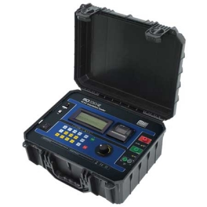
The digital insulation tester model MD-10KVR is Megabras' cutting edge insulation analyzer equipment and it is one of the most complete and sophisticated available in the international market. A powerful software allows for further analysis of tests results, including features such as graphical representation and automatic report generation. Its proven technology provides safe, reliable and accurate measurements of insulation resistances up to 10 TΩ, with 4 pre-selected test voltages, 500 V - 5 kV - 10 kV - 15 kV. Other test voltages may be selected in steps of 25 V, 100 V or 500 V.
A state-of-the-art microprocessor controls the equipment operation and enables the incorporation of advanced features which make measurements easier: auto-range selection, 16,000 readings memory, AC/DC voltmeter, automatic measurement of Absorption Index and Polarization Index, leakage current and capacitance measurement, timer enabling programming of test duration, configurable Pass-Fail test, Step voltage test, real time clock and calendar. Built-in chronometer, indicating elapsed time, in minutes and seconds, since the test started, up to 90 minutes.
Measured values are transmitted through the USB interface and are printed in the built-in printer as a registration of the performed test.The MD-10KVR has a Bluetooth interface that allows remote control of it through a Android device with BlueLogg software. With it you can take the photos of the objects under test and the GPS coordinates of each. It also allows you to record voice comments for each measurement.
Features
- Insulation resistances up to 10 TΩ
- Remote control through an Android app
- Automated tests:
- Absorption index
- Polarization index
- Capacitance
- Leakage Current
- AC/DC voltmeter
- Step Voltage Test
- Real time clock and calendar
- Built-in printer
- 16,000 readings memory
- Software for data management
Specifications
| Specification | MD 10KVR | ||
| Test voltage |
500 V, 1,000 V, 5,000 V, 10,000 V directly, one button selectable. 500 V to 10 kV in 25 V, 100 V or 500 V steps. DC, negative. |
||
| Maximum resistance reading | 10 TΩ @ 5 kV up to 10 kV | ||
| DC Voltmeter |
15 V up to 1,000 Vdc. Accuracy: ±(5% of reading + 3 digits). |
||
| AC voltmeter |
15 V up to 1000 Vr.m.s. Accuracy: ±(5% of reading + 3 digits) |
||
| Overvoltage Category | CAT -III 600V | ||
| Capacitance measurement |
50 nF up to 10 µF @ 500 V. 50 nF up to 5 µF @ 1,000 V. 30 nF up to 2 µF @ 2,500 V. 30 nF up to 1 µF @ 5,000 V. 30 nF up to 680 nF @ 10,000 V. Accuracy: ±10% of reading ± 3 digits. |
||
| Short circuit current | Max. 2 mA | ||
| Test voltage accuracy | ± 3% of nominal test voltages on GΩ | ||
| Insulation tester basic accuracy |
± 5% of reading from 1 MΩ to 1 TΩ @ 10 kV. ± 20% of reading from 1 TΩ to 10 TΩ @ 10 kV. (for lower test voltages, the upper limit will be reduced proportionally) ± 20% of reading ± 5 digits from 10 kΩ to 100 kΩ. ± 10% of reading ± 5 digits from 100 kΩ to 1 MΩ. |
||
| Advanced features |
Automated Polarization Index calculation. Automated Dielectric Absorption Ratio calculation. Programmable Pass-Fail test. Step Voltage Test. 16,000 Readings memory. Switchable filter to remove external noise interference. |
||
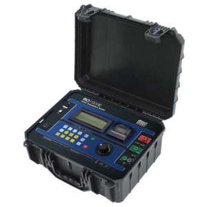
The digital insulation tester model MD-15KVR is Megabras' cutting edge insulation analyzer equipment and it is one of the most complete and sophisticated available in the international market. A powerful software allows for further analysis of tests results, including features such as graphical representation and automatic report generation. Its proven technology provides safe, reliable and accurate measurements of insulation resistances up to 15 TΩ, with 4 pre-selected test voltages, 500 V - 5 kV - 10 kV - 15 kV. Other test voltages may be selected in steps of 25 V, 100 V or 500 V.
A state-of-the-art microprocessor controls the equipment operation and enables the incorporation of advanced features which make measurements easier: auto-range selection, 16,000 readings memory, AC/DC voltmeter, automatic measurement of Absorption Index and Polarization Index, leakage current and capacitance measurement, timer enabling programming of test duration, configurable Pass-Fail test, Step voltage test, real time clock and calendar. Built-in chronometer, indicating elapsed time, in minutes and seconds, since the test started, up to 90 minutes.
Measured values are transmitted through the USB interface and are printed in the built-in printer as a registration of the performed test.The MD-15KVR has a Bluetooth interface that allows remote control of it through a Android device with BlueLogg software. With it you can take the photos of the objects under test and the GPS coordinates of each. It also allows you to record voice comments for each measurement.
Features
- Insulation resistances up to 15 TΩ
- Remote control through an Android app
- Automated tests:
- Absorption index
- Polarization index
- Capacitance
- Leakage Current
- AC/DC voltmeter
- Step Voltage Test
- Real time clock and calendar
- Built-in printer
- 16,000 readings memory
- Software for data management
Specifications
| Specification | MD 15kVr | ||
| Test voltage |
500 V, 5,000 V, 10,000 V, 15,000 V directly, one button selectable. 500 V to 10 kV in 25 V, 100 V or 500 V steps. DC, negative. |
||
| Maximum resistance reading | 15 TΩ @ 10 kV up to 15 kV | ||
| DC Voltmeter |
15 V up to 1,000 Vdc. Accuracy: ±(5% of reading + 3 digits). |
||
| AC voltmeter |
15 V up to 1000 Vr.m.s. Accuracy: ±(5% of reading + 3 digits) |
||
| Overvoltage Category | CAT -III 600V | ||
| Capacitance measurement |
50 nF up to 10 µF @ 500 V. 50 nF up to 5 µF @ 1,000 V. 30 nF up to 2 µF @ 2,500 V. 30 nF up to 1 µF @ 5,000 V. 30 nF up to 680 nF @ 10,000 V. 30 nF up to 680 nF @ 15,000 V. Accuracy: ±10% of reading ± 3 digits. |
||
| Short circuit current | Max. 2 mA | ||
| Test voltage accuracy | ± 3% of nominal test voltages on GΩ | ||
| Insulation tester basic accuracy |
± 5% of reading from 1 MΩ to 1 TΩ @ 15 kV. ± 20% of reading from 1 TΩ to 10 TΩ @ 15 kV. (for lower test voltages, the upper limit will be reduced proportionally) ± 20% of reading ± 5 digits from 10 kΩ to 100 kΩ. ± 10% of reading ± 5 digits from 100 kΩ to 1 MΩ. |
||
| Advanced features |
Dielectric discharge. Ramp test. Automated Polarization Index calculation. Automated Dielectric Absorption Ratio calculation. Programmable Pass-Fail test. Step Voltage Test. 16,000 Readings memory. Switchable filter to remove external noise interference. |
||

