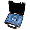
AR700
PD Defect Location in High-Voltage Equipment Insulation by Acoustic Sensors To act on deteriorating insulation the source of PD must be known.The insulation defects produce partial discharges, which emits electrical impulses, radiation of electromagnetic waves as well as acoustic signals.The AR700 measures acoustic signals with multiple sensors spread over the transformer. Then the software determines the failure location using the time difference of all incoming signals. Finally, these coordinates are shown in a 3D model of the transformer. AR700 device is used for measuring of acoustic signals on the external surfaces of gas-insulated breakers and substations, power transformers and other tank high-voltage equipment. The acoustic signals are caused by partial discharges in the insulation, which is the sigh of the defects.The advantage of “AR700” device is the quick installation of the acoustic PD sensors on the external surface of high-voltage equipment tank. The sensors have magnetic holder that is why there is no need to de-energize the equipment for the sensors installation. “AR700” device has 4 syn-chronic channels for acoustic signal measurement. This gives the possibility not only to find the defects in the insulation, but also to locate them. The location function of the “AR700”device is unique for acoustic devices.
Features
- The signal analyses and the PD zone location could be carried out both in manual and automatic modes.
- Software calculates the fault location based on the time difference between the incoming signals.And report is generated about PD source location.
- Convenient and handy through light weight, small size and battery operation.
- Can be used for multiple assets like Transformers, CTs, GIS, Cables etc.
- Defect type identification by synchronised measurement of PD
| Parameter | AR700 |
| Acoustic channels for PD measuring | 4 |
| Frequency range of acoustic sensors | 30 - 300 kHz |
| High-frequency channels for PD measuring | 1 |
| Frequency range of high-frequency sensors | 0.1 - 20 MHz |
| LCD resolution | 480x272pixel |
| PC connection | USB |
| Operating temperature range | -20 to +60 ºc |
| Humidity | <98%, noncondensing |
| Operating time from build-in accumulator | 8 hours |
| Device weight, without sensors | 1.1 kg |
| Dimensions of transportation case | 520x435x230mm |
| Device weight in carrying case | 12kg |
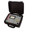
3i
SWITCHGEAR AND CABLE MONITORING SYSTEMS.
The portable multipurpose 3i device (Intellectual Insulation Indicator) is for eff ective high-voltage equipment insulation monitoring on-line. The 3i device measures and analyses partial discharges (PD). For eff ective PD measurement and noise rejection, there are two types of sensors used in the device: the acoustic sensor and the TEV sensor. Both the sensors are built into the device case, and so do not need any connection cables. The device is supplied in a strong metal case; at the faceplate there are the colored screen and two buttons: power button and function button.
Features
- 6 - 35 kV switchgears of various designs;
- Terminations and joints of cables;
- High-voltage gas-insulated equipment (Gas-Insulated switchgear (GIS)) of any rated voltage.
- The tanks of power transformers, breakers, etc.
- The multipurpose 3i device is for on-line insulation condition estimation in the following equipment:
Specifications
| Parameter | 3i |
| In-built PD sensors | acoustic, TEV |
| In-built acoustic sensor frequency range, kHz | 40 ± 2 |
| In-built TEV sensor frequency range, MHz | 10 - 100 |
| LCD resolution, pixels | 240 x 320 |
| PC connection | USB |
| Battery life, hours | 10 |
| Operation temperature range, °C | -20 ÷ 40 |
| Device dimensions, mm | 187 x 78 x 43 |
| Weight, kg | 0.6 |
TRM 50+
SCOPE introduces 50 A state of the art precision winding resistance meter, specially designed for field testing as well as factory testing of large transformers up to 500 MVA. Winding resistance value of transformer and rotating machine are directly displayed on 5.7” TFT display. TRM 50 is designed to work in live EHV switchyard conditions, ensuring operator’s safety and repeatability of results. Maintenance time saving is ensured by one time connection to transformer with simultaneous resistance measurement of three / six windings, measurement of resistances of all taps with automated tap change and demagnetization facility. The meter is protected against the back-EMF offered by large inductive windings.
Features
- Can measure DC winding resistance of large rotating machines, highly inductive test objects like Transformer, Generators and Motors etc.
- 50 A DC current makes it possible to measure low resistances with high accuracy.
- One time connection to either all windings of primary and / or secondary. Simultaneous measurement reduces connection and measurement time.
- Change in winding resistance, short or open windings can be detected from measured values.
- Automatic temperature measurement and temperature corrected value calculation.
- Measurements of winding resistance of all taps of phases in one go. Recoding, printing and storage of results.
- OLTC contact opening and compete OLTC performance test facility. Testing of either single or three phases in one test. Single report generation.
- To know condition of OLTC contacts, OLTC mechanism, transition resistor.
- Discharges and demagnetizes the object after test.
Specifications
| Parameter | TRM 50/ TRM 50+ |
| No of Channels | 3/6 Current Channels, 3/6 Volatge Channels , 1 tempreture Channel |
| Connections | One time connection to primary or secondary winding of transformer |
| Current Ranges | 50A, 40A, 25A, 10A, 5A, 1A, 100mA, 10mA |
| Resistance Ranges | Up to 2000 Ω (Auto ranging) |
| Resolution | 4 ½ digit |
| Accuracy | Value ± 0.5% ± 5 counts |
| Current and Resistance ranges | |
| Open Circuit Voltage | 50 V |
| Demagnetization Facility | Yes |
| Display | 5.7” TFT display with touch screen |
| Printer | 58 mm, Inbuilt thermal printer |
| Communication Port | Ethernet for PC communication |
| Data Port | USB for extrernal memory stick connection |
| External Control | Possible via Notebook PC through Ethernet port and software |
| Temperature measurement | Range 0 to 100 deg, Accuracy ± 1 deg, Resolution 0.1deg |
| Temperature correction | For Aluminium & Copper |
| Temperature Input Channel | Compatible to accept RTD input |
| User Interface | Resistive touch screen |
| Back EMF Protection | Yes. Automatic protection after measurement and during accidental disconnection of current path. Protection operates even if Mains supply fails. |
| Discharge Facility & Indication | Automatic Discharge of DUT & messages on screen |
| Tap Changer Test | Detects discontinuity during tap changer test |
| OLTC Test Facility(Optional) | OLTC test facility with current v/s time graph, Single or Three Phases simultaneously. Available in control through PC option only. |
| OLTC current Ranges | 50A, 40A, 25A, 10A, 5A |
| Protection | Shut down of power source on Over voltage, Over current,Over temperature |
| Indications | Polarity reversal, Test connection continuity and discharge |
| Diagnostics Check | At power On instrument does self-check of channels and shows the message |
| Test Leads | Measuring leads, AC supply, earth leads and temperature sensor lead |
| Operating Environment | -10°C to 50°C, 95% RH (non condensing) |
| Storage Temperature | -20°C to 60 °C |
| Heat Run test | Yes |
| Delta connection Measurement | values of each arm of delta winding is calculated and displayed |
| One side earthing | Instrument is able to do the measurement with one side earthing (with Neutral earthing) |
| Input Supply | 110V AC ±15% 50/60 Hz ±10% Or 220V AC ±15% 50/60 Hz ±10%. |
| Dimensions | 630 x 500 x 302mm |
| Weight | 22 Kg. Approx |
TTRM 302
SCOPE introduces state of the art precision three phase Transformer Turns Ratio Meter (TTRM ) designed for field testing as well as factory testing of power transformers, instrument transformers and distribution transformers of all types. Along with turns ratio, this light weight and reliable instrument measures ratio deviation, phase angle deviation, magnetizing current and detects tap-position of single as well as three phase transformers in charged switchyard condition. The instrument has facility to automatically detect vector group of all majority configurations available. The differant AC voltage selection offers high accuracy in measurement.
Instrument has in-built TFT display with touch screen and thermal printer. The user friendly, simple instrument makes the testing more easy. With the touch keypad it is possible to enter required DUT information. The ratio results of all the phases are displayed in tabular form with % error. Internal non volatile memory gives the provision of storing test results. Further data can be downloaded to PC or copied to memory stick through USB port provided. The CTrans-TTRM software, gives the flexibility to download the stored results to PC and do the further analysis and report generation.
Features
- Different voltage ranges provided for more accurate results
- 5.7” TFT display with touch screen and simple menus to operate TTRM
- Facility to configure transformer ID and details
- Automatic OLTC operation for tap change
- Date and time stamping to results
- In-build memory to store the test results
- Thermal printer to take quick print out for record
- Ethernet port for PC interface to transfer records to PC Software
- Mass storage device (USB 2.0) interface for copying records in pen drive
- Lightweight,portable instrument household in rugged moulded case
Specifications
| Parameter | Display | Range | Resolution | Accuracy | |
| 1 | Turns Ratio | 1.9999 : 1 | 0.8-20000 : 1 | 5 Digit |
0.8 - 100: ± 0.05% @ 10V 101 - 1000: ± 0.05% @ 10V 1001 - 1500: ± 0.05% @ 10V 1501 - 2000: ± 0.10% @ 10V 2001 - 4000: ± 0.20% @ 10V
0.8 - 100: ± 0.05% @ 40V 101 - 1000: ± 0.05% @ 40V 1001 - 1500: ± 0.05% @ 40V 1501 - 2000: ± 0.05% @ 40V 2001 - 4000: ± 0.05% @ 40V 4001 - 13000: ± 0.25% @ 40V
0.8 - 100: ± 0.03% @ 100V 101 - 1000: ± 0.05% @ 100V 1001 - 1500: ± 0.05% @ 100V 1501 - 2000: ± 0.05% @ 100V 2001 - 4000: ± 0.05% @ 100V 2001 - 4000: ± 0.05% @ 100V 4001-13000: ± 0.15% @ 100V 13001 - 20000: ± 0.20% @ 100V |
| 2 | Excitation Current | 0.1mA to 1.999A | 0-2A | 0.1mA | ± 1mA |
| 3 | Phase Deviation | 0.05 Deg to +179.95 Deg | ± 180 Deg | 0.05 Deg | ± 0.05 Deg |
| Parameters | TTRM 302 |
| No of channels | Three HV channels and three LV channels |
| Test Voltages | 10V, 40V and 100V AC selectable voltages |
| Measurements |
Ratio, Ratio error, Phase Angle Deviation, Excitation current, Vector group and Magnetic balance (optional) |
| OLTC Control | Raise and Lower control to operate OLTC |
| Test Results Display | 5.7” touch-screen (TFT) display, thermal printer |
| Test Leads | Suitable to test EHV Transformers |
| Paper | Thermal, 58 mm wide roll form |
| Memory | Up to 50000 records inbuilt memory, with date and time stamping |
| Power | (110V ± 15%) / (60Hz ± 10%) OR (230V ± 15%) / (50Hz ± 10%), 75VA. |
| Communication Port | Ethernet port for PC Communication, USB port for data downloading to pen-drive |
| Housing | IP 65 rated moulded case |
| Operating Environment | -20°C to +55°C, 95%RH (non-condensing) |
| Storage Environment | -40°C to +60°C, 95%RH (non-condensing) |
| Dimensions | 435 X 315X 175 mm. (Max.) |
| Weight | 10 Kg Approx |
SA 30i+
SA 30i+, the wireless Leakage Current Analyser from SCOPE is a State of the Art, On-line test system for Residual Life Assessment of Metal Oxide Surge Arresters. The instrument measures and directly displays the values of Total Leakage Current and Third Harmonic Resistive Leakage Current. It provides system harmonic compensation as per IEC 60099-5-B2. It provides Corrected Resistive Leakage Current after applying correction factors for change in system voltage & temperature.
The SA 30i+ can be pre-loaded with the LA identity details (LA Identification, Type, Serial Number,Location, Rated Voltage etc.) and tests conducted on the same ID of the arresters are saved under the same folder. Trend analysis software, SAData picks up this data and stores them in a similar fashion on a PC. This analysis software enables the user to take a decision to repair/replace the arresters considering safety limits.
SA 30i+ is designed to work under the hostile electrostatic noise found in live EHV switch yards upto 765 kV
Features
- Safe Online measurement due to wireless CT and Field Probe
- In built temperature measurement facility enables calculation of temperature corrected leakage currents.
- Correction of results to rated voltage of LA to eliminate eff ect of change in system voltage.
- Date and time stamp on test results Results are displayed on large font, Big, back-lit LCD, printed on in-built thermal printer and can be stored in memory of the instrument.
- SA 30i+, CT unit and Field Probe unit are powered by easily available re-chargeable Lithium-ion batteries. It works for a day’s testing needs on a single charge
- The SA 30i+ is a switchyard compatible instrument. This makes the instrument extremely convenient to use.
- Built-in standard calibration source and self-calibration check facility
- USB communication port to transfer data to PC and Windows based PC Downloading & Analysis Software.
- Facility for testing of GIS LAs available optionally
Specifications
| Parameter | SA30i+ |
| Total Leakage Current Range | 1 μA to 20 mA |
| Resistive Leakage Current Range | 1 μA to 20 mA |
| Resolution | 1 μA |
| Accuracy | Value ± 5% ± 1 μA |
| Inputs | Wireless Clamp on CT and Wireless Field Probe optional external field PT Input (Voltage Peak method as per IEC 60099-5-A1 for GIS) |
| Display | 4 line x 20 character large backlit LCD with large font |
| Compensation | Automatic for System Harmonics, Temperature & System Voltage |
| Temperature Sensor |
Inbuilt Platinum Resistance Thermometer |
| Self-calibration Check | Available |
| PC Connectivity | USB Port (Standard), RS 232 & Ethernet (Optional) |
| Memory | Storage capacity of 2000 results |
| Printer | 58mm Inbuilt Thermal Printer |
| Power |
Battery as well as Mains powered Main Unit Battery powered CT and FP Units |
|
Internal Battery |
SA30i+ - 11.1 V / 4400mAh Internal Rechargeable battery, CT Unit - 11.1 V / 2200mAh Rechargeable battery, Field Probe Unit - 11.1 V / 2200mAh Rechargeable battery. 8 hours Battery life with full charge |
| Mains Supply | 88 to 264 VAC, 47 to 63 Hz, Single Phase |
| Battery Charger | Inbuilt in Main Unit, Connection to CT and Field Probe Provided |
| Dimension
|
SA30i+ - 350 x 295 x 150 mm, CT Unit - 366 x 85 x 43 mm, Field Probe Unit - 340 x 95 mm Cylindrical |
| Weight
|
SA30i+ - 5.0 Kg, CT Unit - 0.7 Kg , Field Probe Unit - 1.2 Kg |
| Environment |
-20°C to 55°C, up to 95% RH (non-condensing), Storage Temp - 0-70°C |
|
Type Testing |
As per IEC 60068 / IS 9000 for Dry Heat, Damp Heat, Change of Temperature, Bump, Vibration and Mechanical Shock. For EMI / EMC & Safety as per relevant IEC Standards |
SIM Filter
The CFL SIMF+, Cable Fault Secondary Impulse Filter from SCOPE is the ultimate solution for locating underground cable faults in minimum time. It uses advanced technology for fault distance measurement which helps even an unskilled operator to locate the fault accurately.
Cable Fault Secondary Impulse Filter CFL SIMF+ is mainly used for high resistance and flashing fault test for power cable with the voltage below 10kV, and for fault location with Secondary Impulse with the conjunction of Pre-locator and HV surge generator. Latest fault locating technique for high resistance and flashing faults is Secondary Impulse Method (SIM). This method offers highly reliable results for faults on any type of power cable. It converts the faults to low resistance nature by creating an arc across the fault.
It is a passive filter having its own output power source. It uses the energy of the surge generator to create an arc at the fault point. A high voltage switch incorporated in the output circuit facilitates selection of SIM or ICM mode.
Audio Generator
The new generation CFL AG2 Cable Fault Audio Generator from SCOPE is the ultimate solution for locating the underground cable lay in minimum time. It uses advanced technologies for auto impedance matching, and stabilised frequency which helps even an unskilled operator to locate the cable accurately.
CFL AG2 portable Audio Generator to locate the exact route of the underground cable in conjunction with Pin Pointer cum Rote Tracer i.e., CFL PP Series. This configuration is also used for depth determination of the cable and pinpointing of low resistance faults. Various modes of operation combined with advanced features offer users the most effective solution for the job.
Features
- Compact, Lightweight and Rugged
- Operation via User Friendly Interface
- Variable output power up to 20 Watt
- Automatic load matching
- Works eff ectively with high impedance loads
- Quartz Stabilised Frequency
- Continuous or Pulsed signal injection
- Over current protection
- Water resistant and dust proof design
Specifications
| Parameters | CFL AG2 |
| Output Power | 20W Maxiumum |
| Maxiumum Output Current | 2.8A±20% |
| Frequency | 1KHz sine wave |
| Output Voltage | 4-7V/15-25V/30-40V/60-70V/90-100V/150-170V/200-230V |
| Display | Analog Meter for Output Current |
| Input Power Supply | AC 230V ±10%, 50Hz ±10% |
| Protection | Over Current / Load |
| Environmental (Operation) | 0°C to 50°C, 95% RH (Non-Condensing) |
| Environmental (Storage) | -10°C to 60°C, up to 98% RH (Non-Condensing) |
| Dimension | 275mm x 255mm x 130mm |
| Weight | 4kg |
CFL PL4
Underground cable faults cannot be avoided due to many factors such as road widening, infrastructure improvement, digging carried out for repairs of other underground utilities etc.
The new generation CFL PL4 Cable Fault Prelocator from SCOPE is the ultimate solution for locating underground cable faults in minimum time. It uses advanced technology for fault distance measurement which helps even an unskilled operator to locate the fault accurately.
CFL PL4 portable Prelocator is used for identification of fault types in underground cables and the distance of fault. These products are designed to fi nd out various types of faults in the cable such as Open Circuit, Short Circuit, Splice in Cable, High Resistance, Moisture Ingress, etc. Various modes of operation combined with advanced features off ers user the most effective solution for the job.
Features
- User friendly operation
- Wide measurement range up to 64km
- Highest measurement accuracy of ±1% of selected range
- High speed sampling of 200MHz
- Automatic Cable End detection
- Automatic Fault Point detection
- Zoom function for detailed analysis of the waveform
- Asynchronous interference & noise suppression
- Adjustable Gain and Balance
- Inbuilt memory to store 300 waveforms with USB connectivity
- "Print-screen" function to save image in JPG
- PC Software for waveform analysis and report preparation
- High resolution 8” Colour Touchscreen display
- Mains as well as Inbuilt Rechargeable Battery operated
- Housed in weather proof molded case
Specifications
| Parameters | CFL PL4 |
| Modes of Operation |
TDR SIM / MIM / ARC (Up to 8 Fault Traces) ICM/ICE Voltage Decay |
| Sampling Rate | 200 MHz |
| Measurement Range | Up to 64 km |
| Measurement Accuracy | ±1% |
| Best Resolution | 1m |
| Pulse Amplitude (OCV) | 30V |
| Pulse Width | 40nS to 10µS |
| Output Impedance | 5Ω to 87Ω |
| Velocity of Propagation (V) | 90 - 300 m/µs |
| Memory | 300 Waveforms |
| Connectivity | USB, Direct Download to Pen drive |
| Display | 8” Colour Touchscreen LCD |
| Battery | Rechargeable Lithium Ion, Suitable for 8 hour operation |
| Power Supply | 90V to 264V AC, 47 to 63 Hz, Single Phase |
| Environmental (Operation) | -10°C to +50°C, up to 95% RH (Non-Condensing) |
| Environmental (Storage) | -20°C to 70°C, up to 98% RH (Non-Condensing) |
| Dimension | 339mm x 295mm x 152mm |
| Weight | 4.5 kg |
HISAC Ultima
HISAC Ultima – new generation Circuit Breaker Dynamic Test Set from SCOPE …. The ultimate solution for testing Circuit Breakers of all types. HISAC Ultima is the most complete analyser for checking the dynamic performance of CBs in live EHV switchyards upto 765 kV.
HISAC Ultima can carry out Dynamic Contact Resistance Measurement on SIX breaks of THREE poles in one operation thereby significantly reducing stress on CB & testing downtime.
It offers flexibility to create pre-programmed Test Plans including all test settings for all types of circuit breakers available in a switchyard that can simply be recalled at the time of actual testing. This saves you from doing all settings in switchyards.
The Analysis software offers a range of utilities which enables effective Condition Monitoring of CB by comparing present test data with previous signatures and predicting future performance.
Features
- Tests all types of circuit breakers - LV, HV & EHV for all critical performance parameters of all the poles / breaks in a single shot.
- Measures Main/PIR contact timings, bounce, non simultaneity of contacts and auxiliary contact timings.
- Analyses contact travel characteristics for speed, insertion, contact gap, over-travel and rebound with suitable transducer and mounting fixture.
- Records trip and close coil current characteristics.
- Registers the signature of Dynamic Contact Resistance of main and arcing contacts, of all the 6 breaks simultaneously.
- Displays settings, graphical and tabulated test results.
- Prints test report in graphical format with test header and calculation footer, on external printer(not supplied).
- Incorporates powerful and practical Windows™ based Test Manager Software to control & operate instrument; view, analyze and handle graphical test data on a laptop at high resolution.
- Selects pre-programmed setup parameters and pass/fail limits through software.
- Connects to CB with wear resistant test leads of sufficient length, having quick-fit connectors, suitable for EHV circuit breakers.
- Moves easily within switchyard as the set can be mounted on a specially designed Trolley having large wheels & mains supply distribution board.
- Travel – For evaluating travel characteristics of operating mechanisms, SCOPE offers rotary and linear resistive travel transducers with universal / specially designed fixtures to suit variety of CBs available.
- DCRM module captures dynamic variation in contact resistance of main & arcing contacts during breaker operation.
- Each DCRM module has in built independent isolated, rechargeable battery based 100A DC source.
- The result is plotted in graphical form on the software screen, which can be further analysed for finding parameters such as contact gap, total insertion, arcing tip insertion, main and arcing contact resistance values etc.
- Additional optional modules are available to measure PIR value and for monitoring Station DC (Coil voltage), Motor current or other static parameters through configurable Analog channels.
- Type Tested as per IEC 60068, IEC 61326 & IEC 61010-1. CE marked
- Supplied with suitable Test Leads & aluminium transport cases for instruments.
- Travel Transducer and fixture as per order based on make, type & rating of CB.
Specifications
| Parameter | HISAC Ultima |
| Trigger Options | O, C, C-O, O-C, O-C-O |
| Timing Channel | 24 : 4 Main + 4 PIR per pole, 3 poles Simultaneously |
| Auxiliary Contact Timing Channel | 8 : 4 dry + 4 wet Expandable up to 6 Dry + 6 Wet |
| Best Time Resolution | 50μS |
| Coil Current Channel | 3 : Trip / Close coil current optionally expandable up to 6 |
| Travel Channel | 3 : Travel characteristic optionally expandable up to 6 |
| Analog Channel for DCRM Input (Optional) | 1 / 2 / 3 / 6 – as per DCRM modules selected |
| DCRM Resistance Range & Current (Optional) | 1000 / 2000 / 4000 / 8000 μΩ Selectable, Current 100A DC |
| Static Contact Resistance (CRM) Channel | As per DCRM modules selected |
| CRM Resistance Range | 1000 / 2000 / 4000 / 8000 μΩ Selectable |
| Configurable Analog Channel (Optional) | Up to 6: For inputs of station battery voltage, PIR value etc. |
| PIR value Measurement (Optional) | 0-5000Ω with the resolution of 1Ω |
| Sampling Speed | 1 / 2 / 5 / 10 / 20 kC Selectable |
| Display | Display of laptop |
| Operation | Interactive menu through laptop |
| PC Connectivity | Ethernet |
| Printer | External through laptop |
| Memory | Memory of laptop |
| Dimensions | Analyser - 500 x 270 x 300 mm, DCRM Rack - 500 x 270 x 250 mm |
| Instrument Weight | Analyser - 12 kg DCRM Rack-18 Kg(3 DCRM modules per Rack) |
| Power | 230 V AC ± 15% , 50Hz ± 10% |
SCOT M3K
SCOT series of CB Time Interval Meters from SCOPE are compact and reliable instruments to measure operating time of all types of HV/EHV circuit breakers under charged swichyard conditions up to 400kV.
SCOT M3K measures and displays CLOSE, OPEN and CLOSE-OPEN time of main contacts of 3 poles connected end to end, simultaneously.
Features
- Inbuilt clock to tag date and time of test to the readings
- 4 line 20 character backlit LCD display for menu and results
- Inbuilt memory to hold results of last fi fty tests
- Easy to use menu driven user interface for operating
- Diagnostics for instrument condition and calibration watch
- Select the operation and mode to be performed e.g. Close, Open or CLOSE-OPEN
- Operation times of all three poles are measured and displayed simultaneously on the display
- Test results can be stored and downloaded to a PC using SCOPE’s CDATA software
Specifications
| Parameters | SCOT M3K |
| Channels | 3 |
| Breaker Control | Solid state contacts rated 300V / 30A for breaker operation |
| Output | 4 line 20 character backlit LCD RS 232C port for downloading data to PC |
| Range | 999ms maximum |
| Resolution | 1ms |
| Measuring Accuracy | Value ± 0.05% ± 1 digit |
| Test Leads | Set of 15m, wear resistant Test Cables |
| Environment | 0° to 50° C, 95% RH (Non-condensing) |
| Power | 230V AC ± 15%, 50Hz ± 10%, 25 VA |
| Dimensions | 430 x 345 x 160 mm |
| Instrument Weight | 4 kg |