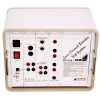
EM 4058
The EM-4058 earth tester is a digital, microprocessor controlled instrument that allows to measure the earth resistance and ground resistivity (using Wenner´s method), as well as to detect parasitic voltages present in the ground. This instrument is suitable to measure earth systems in power substations, industries, distribution networks, etc., according to IEC 61557-5.
In order to conveniently test the earth system, EM4058 allows to perform measurements using the test current which frequency may be operator-selected (270 Hz, 570 Hz, 870 Hz, 1170 Hz or 1470 Hz). On one hand, the lowest frequency will allow to analyze the earth system behavior related to fault currents of industrial frequency, while on the other hand, the measurement performed with the highest frequency will best show the behavior in connection with electrical currents caused by lightning and will offer a very high immunity related to interference voltages that are usually present in soils, specially near substations.
The instrument has four ranges that are automatically selected, covering measurements from 0.01 Ω up to 20 kΩ, which allows to obtain very accurate measurements for any kind of soils. During ground resistivity measurement, the operator may indicate the distance between spikes in order for the equipment to apply Wenner's formula and to show the resistivity value directly.
Features
- Earth resistance measurement
- Ground resistivity (Wenner's method)
- High spurious voltage rejection
- Spurious voltage measurement
- Measure with multiples frequencies (270 Hz, 570 Hz, 870 Hz, 1170 Hz, 1470 Hz)
- 0.01 Ω resolution
- Up to 20 kΩ resistance range
- Remote control through an Android App
- Auto-range
- Built-in memory
- Built-in printer
- USB interface
Specifications
| Specifications | |||
| Measurement ranges |
Resistances: 0-20 Ω; 0-200 Ω; 0-2,000 Ω; 0-20 kΩ (Auto-ranging) Resistivity : 0- 50 kΩm (auto ranging) Voltage: 0-60 V~ |
||
| Accuracy |
Resistance & Resistivity measurements: R ≤ 2 kΩ: ± (2% of the measured value ± 2 digits). Voltage measurements: ± (2% of the measured value + 1% of end of scale value). |
||
| Reading resolution |
0.01 Ω in the resistance measurement; 0.01 Ωm in the resistivity measurement; 0.1 V in the voltage measurement. |
||
| Output Current | The short-circuit current is limited to less than 20.0 mARMS (according the IEC 61557-5 - 4.5). | ||
| Operation Frequency |
270 Hz (resistance or resistivity measurement) 570 Hz, 870 Hz, 1170 Hz or 1470 Hz (resistance measurement) Max. variation: ± 1 Hz (both cases). |
||
| Battery charger | A smart, microprocessor controlled, circuit adjusts the battery charge to the optimised parameters in order to ensure the maximum service life. It is supplied by means of an external AC adapter (provided with the equipment) or from a 12 V car battery. | ||
DecR
SCOPE offers High Resistance, High Voltage Decade Resistance Box - DecR. It contains number of smartly configured precision resistors. They are arranged in such a way that user can obtain desired resistance value by selecting appropriate decade switches. DecR is designed using the high quality specially selected resistors. These range of high ohm resistance decades are ideal for variety of applications, having a voltage rating up to 5 kV. It covers the resistance range from 1 kilo ohm to 1 tera ohm. DecR can also be customized as per requirement. DecR is housed in a rugged case and available in 3 / 4 / 6 / 9 decades or in binding post configuration
DC Trace
SCOPE introduces DC Trace, the most advanced and user friendly DC Earth (Ground) Fault Locator. This portable instrument consisting of Signal Generator & Signal Receiver (DC TraceR) uses latest digital signal processing technology. It’s ability to detect earth faults in live DC system quickly & accurately in online condition greatly relieves the substation maintenance engineers from nightmare of earth leakages & it’s detection.
Its capability to detect the high resistance faults upto 1MΩ, helps to detect fault at incipient stage. Use of two current sensing clamps pinpoint fault quickly by eliminating interference. It is an excellent solution for preventive maintenance & troubleshooting of ground faults.
Features
- Touchscreen operation on colour graphical LCD
- Online fault detection, no shut-down required
- Signal Generator with adjustable output voltages from 24V to 1000V, suitable for different applications
- Pinpoints high grounding resistance faults up to 1MΩ
- Digital Signal Processing Technology for detecting grounding resistance and distributed capacitance
- 10Hz output frequency on the signal receiver effectively avoids interference from the DC system
- Frequency Spectrum Analysis for detection of surrounding frequencies
- A signal Receiver with adjustable sensitivity at different locations of the circuit helps to locate the current leakage quickly
- Direction (forward/reverse) indication for leakage current helps quick tracing of the faulty grounding path
- Multiple analysis & indications for easy ground fault identification:
- Direction of current flow
- Phase angle difference
- Comparison of signal strength
- Detection of complex, multipoint and DC source mixing faults
- Multiple receivers can work simultaneously with single generator
Specifications
| Parameter | DC Trace | |
| Output Voltage | 24 /48 /110 /220 /500 /1000V | |
| Output Frequency | 10Hz | |
| Current Sensitivity | ≥0.5mA | |
| Display | Generator | 320 × 240 pixel, 3.5” colour LCD screen |
| Receiver | 240 × 320 pixel, 3.5” colour TFT touch screen | |
| Battery Life | ≥4 Hrs | |
| Battery Charging Input | 230V / 110V AC, 50 / 60Hz | |
| Working Environment |
0°C to 50°C, <95% RH (non-condensing) |
|
| Dimension |
Generator | 275 X 255 X 130 mm |
| Receiver | 210 X 110 X 60 mm | |
| Clamp | Dual Range CT: 56mm (jaw opening), Ø 65 x 30mm and Ø12 x 8mm | |
| Weight | Generator | 2.5kg |
| Receiver | 0.65kg | |
| Clamp | 0.6kg | |
BLUe
BLUe series Battery Loading Units; portable instruments for controlled & monitored discharge of batteries. It is designed for integrated site discharge test, design & QC test and also for monitoring discharge process of battery bank with connected load. Single autonomous unit having inbuilt display, keypad and wireless communication with PC makes it very easy to use. It comes in different configurations ranging from 12V to 380V discharge voltages and 50A to 300A discharge currents. Various options are available to control & monitor the discharge process. With the help of optional Cell Monitoring Unit - CELLMon, voltage of each individual cell can be monitored & data sent to main BLUe unit and then from main unit to PC via wireless communication. Each BLUe unit is supplied with PC downloading & analysis software for real time monitoring of discharge process.
Features
- Portable unit with rolling wheels thus convenient for onsite testing.
- Optional wireless CELLMon enables the process PC monitoring both for discharging and charging.
- BLUe sets 4 conditions for auto shut-down of discharge process so secured and time-saving operation.
- Continue discharge facility is available when previous discharge is stopped abnormally.
- Parallel connection of two discharging units for mass discharge.
- Real-time display of voltage for each cell with the help of Cell Monitoring Unit, CELLMon.
- Accurate data results and vivid waveforms.
- Auto sorting for lag-out batteries during discharging.
- AC & DC power supply modes for diǑerent needs.
- Integrated functions for displaying, controlling and discharging.
- Safe circuit design to avoid damage of battery when testing.
- Direct USB drive for convenient data transfer to PC.
- Powerful battery discharge monitor software for data analyzing and report printing
- Thermal cut-off and automatic overload protection.
- Customised Models available other than standard 15 models
CRM 100B+
SCOPE introduces its next generation of hugely popular CRM series contact resistance meter, CRM100B+ in all new super light avatar, based on cutting edge ultra capacitor technology. CRM incorporates some state of the art hardware & smart software features making it a must have tool for testing & maintenance engineers.
CRM directly measures micro-ohm values at 100A DC under live EHV switchyard conditions quickly & accurately. It is specially designed to reliably measure micro-ohm contact resistances of Circuit Breakers, Isolators, Busbar joints, earth switch joints, welded joints etc., under the hostile electrostatic noise found in live EHV switchyards up-to 765 kV. SCOPE’s ability to make electronics work in such environment enables CRM to measure mili-volts signal in the presence of kilo-volts noise.
CRM is equally suitable for MV / HV / EHV equipments and is very useful to Power Companies, Equipment Manufacturers, Testing & Commissioning Companies and Test Laboratories etc.
Features
- A radically new design makes CRM the lightest available contact resistance meter.
- Simultaneous & multiple samples of test current and voltage drop are taken at high speed using fast & high resolution ADCs.
- Resistance will be calculated by taking actual V/I ratio and averaging of individual samples giving stable & accurate results. It makes it independent of test current variations.
- Autoranging. Direct display of micro-ohm value does away with manual calculations.
- In built real time clock, memory and printer. Test time stamping on each record enables time references for future use.
- Fool-proof connections and repeatability are ensured by SCOPE’s specially designed proprietary Ck clamps.
- Supplied with rugged calibrated test lead set suitable for 4 wire measurement.
- Optimised test lead set design gives lengths enough for testing EHV CBs, yet are lightweight.
- Mains as well as battery operations
- Protection against battery deep discharge.
- Simple operation. Tests can be conducted even by technicians.
- Instrument is continuously available for measurements one after the other. No ON/OFF duty cycle.
- Enclosed in ultra rugged IP67 class hard moulded case.
- PC Downloading & Analysis including ‘Trend Analysis’ possible with “CData CRM+” Software supplied with kit.
- Instrument debug options like memory check, printer check, PC downloading check are provided.
Specifications
| Parameter | CRM 100B+ |
| Test Current | 100A plus. Peak Test Current will be decided by the load resistance, however 100A minimum is guaranteed |
| Resistance Range | 0 - 200µΩ, 2000µΩ, 20mΩ, Autoranging |
| Resolution | 0.1µΩ, 1µΩ & 10µΩ for above range respectively |
| Accuracy | Value ± 2% ± 1 Digit |
| Output Voltage (max) | 10V DC |
| Operation Mode | Stand Alone & PC Control |
| Display | 4 Line X 20 character LCD. 3 ½ digit display for Test Current & Resistance |
| Printer | In-built Thermal Printer |
| Memory | 1000 records Internal |
| In-Built Battery | Li-Ion, 11.1V, 6 Ah |
| Power |
Input to Battery charger: 90-275V AC , 50Hz ±10%, 100 to 300V DC Charger output - 13.5 V DC, 1500 mA Max |
| Communication Port | USB |
| Software | CData CRM - For PC Control & PC Control, Downloading & Analysis, Windows based |
| Environment | 0 to 50°C, up to 95% RH (non-condensing) |
| Dimension | 340 x 295 x 155 mm |
| Weight | 4kg |
CRM 200B+
SCOPE introduces its next generation of hugely popular CRM series contact resistance meter, CRM200B+ in all new super light avatar, based on cutting edge ultra capacitor technology. CRM incorporates some state of the art hardware & smart software features making it a must have tool for testing & maintenance engineers.
CRM directly measures micro-ohm values at 200A DC under live EHV switchyard conditions quickly & accurately. It is specially designed to reliably measure micro-ohm contact resistances of Circuit Breakers, Isolators, Busbar joints, earth switch joints, welded joints etc., under the hostile electrostatic noise found in live EHV switchyards up-to 765 kV. SCOPE’s ability to make electronics work in such environment enables CRM to measure mili-volts signal in the presence of kilo-volts noise.
CRM is equally suitable for MV / HV / EHV equipments and is very useful to Power Companies, Equipment Manufacturers, Testing & Commissioning Companies and Test Laboratories etc.
Features
- A radically new design makes CRM the lightest available contact resistance meter.
- Simultaneous & multiple samples of test current and voltage drop are taken at high speed using fast & high resolution ADCs.
- Resistance will be calculated by taking actual V/I ratio and averaging of individual samples giving stable & accurate results. It makes it independent of test current variations.
- Autoranging. Direct display of micro-ohm value does away with manual calculations.
- In built real time clock, memory and printer. Test time stamping on each record enables time references for future use.
- Fool-proof connections and repeatability are ensured by SCOPE’s specially designed proprietary Ck clamps.
- Supplied with rugged calibrated test lead set suitable for 4 wire measurement.
- Optimised test lead set design gives lengths enough for testing EHV CBs, yet are lightweight.
- Mains as well as battery operations
- Protection against battery deep discharge.
- Simple operation. Tests can be conducted even by technicians.
- Instrument is continuously available for measurements one after the other. No ON/OFF duty cycle.
- Enclosed in ultra rugged IP67 class hard moulded case.
- PC Downloading & Analysis including ‘Trend Analysis’ possible with “CData CRM+” Software supplied with kit.
- Instrument debug options like memory check, printer check, PC downloading check are provided.
Specifications
| Parameter | CRM 200B+ |
| Test Current | 200A plus. Peak Test Current will be decided by the load resistance, however 200A minimum is guaranteed |
| Resistance Range | 0 - 200µΩ, 2000µΩ, 20mΩ, Autoranging |
| Resolution | 0.01µΩ, 0.1µΩ & 1µΩ for above range respectively |
| Accuracy | Value ± 1% ± 1 Digit |
| Output Voltage (max) | 17.5V DC |
| Operation Mode | Stand Alone & PC Control |
| Display | 4 Line X 20 character LCD. 4 ½ digit display for Test Current & Resistance |
| Printer | In-built Thermal Printer |
| Memory | 1000 records Internal |
| In-Built Battery | Li-Ion, 11.1V, 6 Ah |
| Power |
Input to Battery charger: 90-275V AC , 50Hz ±10%, 100 to 300V DC Charger output - 13.5 V DC, 1500 mA Max |
| Communication Port | USB |
| Software | CData CRM - For PC Control & PC Control, Downloading & Analysis, Windows based |
| Environment | 0 to 50°C, up to 95% RH (non-condensing) |
| Dimension | 340 x 295 x 155 mm |
| Weight | 5kg |
CRM 100C
CRM 100C directly measures resistance values with DC current injection under live switchyard conditions.The CRM 100C is specially designed to reliably measure contact resistance of Circuit Breakers, Isolators, Bus Bar joints, welded joints etc., under the hostile electrostatic noise found in live EHV switchyards. It can also be used for testing cables, graphite bars etc.
It has a truly continuous current source without any ON/OFF duty cycle
Features
- Innovative design makes CRM 100C the lightest available continuous current contact resistance meter
- Direct display of micro-ohm value does away with manual calculations
- Fool-proof connections and repeatability are ensured by SCOPE’s specially designed proprietory Ck clamps
- Supplied with rugged calibrated test lead set satisfying Kelvin’s 4 wire measurement principle.
- Selectable current ranges allows user to test various DUTs having wide resistance range.
- Every current range is associated with selectable resistance range to achieve better resolution of results.
- LED indication makes user aware about current injection status.
- User-friendly Menu structure enables user to take test easily.
- PC downloading facility is available with CData – PC Downloading & Data Management Software.(Optional)
Specifications
- Current : 10, 20, 50, 100A DC
- Accuracy : Value ± 0.5 % ± 5 digit
- Display : One backlit 4 line LCD for interactive menu, test results, keyboard functions and messages,test results, 3½ digit for resistance and current values
- Power : 230 V AC ± 15%, 50 Hz ± 10%, 500 VA
- Dimensions : 475 x 405 x 175 mm
- Weight : 11 kg, instrument
- Environment: 0° to 50° C max, 95 % RH (non-condensing), Live EHV switchyard environment
- Ranges : On SCOPE’s Calibrated Test Leads as follows
| Test Current | Resistance Range | Resolution |
| 100A |
199.9µΩ 1999µΩ 19.99mΩ |
0.1µΩ 1µΩ 0.01mΩ |
| 50A | 1999µΩ
19.99mΩ |
1µΩ
0.01mΩ |
| 20A | 1999µΩ
19.99mΩ 199.9mΩ |
1µΩ
0.01mΩ 0.1mΩ |
| 10A | 19.99mΩ
199.9mΩ 1999mΩ |
0.01mΩ
0.1mΩ 1mΩ |
CRM 200B
CRM 200B directly measures micro-ohm values at 100 Amps DC under live switchyard conditions.
CRM 200B is specially designed to reliably measure contact resistance of circuit breakers, isolators, busbar joints, welded joints etc., under the hostile electrostatic noise found in live EHV switchyards upto 765 kV.
Inbuilt rechargeable battery tremendously enhances utility as AC supply connectivity is not required.
CRM 200B operates on a rechargeable battery as well as Mains supply. It has a built-in constant current source, a precision instrumentation amplifi er, digital readout and control logic.A pulse of 200A DC is passed through the test object and voltage drop is sensed using the classical Kelvin’s 4 wire method to measure contact resistance. Both test current and resistance value are displayed on LCD.
Features
- A radically new design makes CRM the lightest available contact resistance meter
- Battery as well as Mains operated
- Direct display of micro-ohm value does away with manual calculations
- Fool-proof connections and repeatability are ensured by SCOPE’s specially designed proprietary Ck clamps
- Supplied with rugged calibrated test lead set suitable for 4 wire measurement
- Additional range of 20 mΩ is provided
Specifications
- Ranges : 199.9μΩ, 1999μΩ and 19.99mΩ
- Resolution : 0.1μΩ,1μΩ and 10μΩ respectively
- Accuracy : Value ± 1% ± 1 digit
- Current : 200 A DC
- Displays : Two, 3½ digit, ½ inch LCD, for current and resistance values
- Power : 230 V AC ± 15%, 50 Hz ± 10%, 75 VA
- Battery : Instrument operation on inbuilt , rechargeable battery (2 nos. 6V, 4.5Ah)
- Dimensions : 435 x 350 x 170 mm
- Weight : 9 kg, instrument
- Environment: 0° to 50° C max, 95 % RH (non-condensing), Live EHV switchyard environment
DIR CT
SCOPE proudly introduces Dir CT, a CT Polarity Tester specially designed to verify correctness of polarity of current transformers cores in live EHV switchyards. Polarity test is one of the most common yet crucial tests required to be done on current transformers by commissioning as well as maintenance engineers. Even though it is commonly conducted check, there was no all in one simple tool available for this measurement. DIR CT fills this void to perfection, it is expected to significantly reduce the time taken for polarity checks on numerous CT in sub-station, especially during commissioning of new sub-stations
It is must have tool for Testing & Commissioning companies.
Features
- Simple, Portable, Lightweight, Handheld device.
- Easy and fast one push-button operation.
- Gives analog indication (Forward & Reverse) of current transformer polarity.
- Tests various types of CTs.
- Works on easily available AA size alkaline batteries.
- Gives reliable performance even after continuous usage
TRM 104
TRM104 is a portable winding resistance meter, designed to work in live EHV switchyards. Winding resistance values of large transformers up to 500 MVA and rotating machines are directly displayed. The meter is protected against the back emf offered by large inductive winding. A back-lit 4 line LCD with a user-friendly menu sets up the instrument for the test. Winding resistances and safety messages are also shown on this display. It is possible to measure the resistance of two windings simultaneously.The meter contains a special power source for rapid stabilization of test results.
A 30V DC, 10 Amp power source, controlled strategically by digital means passes the selected current through the winding. Precision instrumentation amplifiers read voltage developed across the windings and the ohmic values are directly displayed. Use of the classical Kelvin’s 4-wire method ensures reliable measurement. Specially designed thermal management of power source enables measurement over longer periods, when delta connected generator transformers are tested. The TRM is capable of identifying the interruption of injected current during tap change of OLTC. A beeper alarm during current injection ensures operator safety during measurement.
Features
- Winding resistance values of large transformers upto 500 MVA and rotating machines are directly displayed.
- Portable winding resistance meter, designed to work in live EHV switchyards.
- Protected against the back emf off ered by large inductive windings.
- A backlit 4 line LCD with a user-friendly menu sets up the instrument for the test. Winding resistances and safety messages are also shown on this display.
- Possible to measure the resistance of two windings simultaneously.
- The meter contains a special power source for rapid stabilisation of test results
Specifications
| Parameter | TRM 104 |
| No of Channels | Two, for simultaneous measurement on 2 windings |
| Current Ranges | 10A, 1A, 100mA, 10mA |
| Resistance Ranges | Up to 2000 Ω (Auto ranging) |
| Resolution | 4 ½ digit |
| Accuracy | Value ± 0.5% ± 2 digits |
| Open Circuit Voltage | 30 V |
| Display | One backlit 4 line LCD display for interactive menu |
| Test Leads | 20m, suitable to test HV/EHV transformers |
| Environment | 0°C to 50°C, 95% RH (non condensing) |
| Input Supply | 230 VAC ± 15%, 50 Hz ± 10%, 400 VA approx |
| Dimensions | 475 x 405 x 230 mm |
| Weight | 15 Kg. Approx |